Right about the band, wrong about the path
In 1901, on two hundred acres of Long Island scrubland, Nikola Tesla began building the first station of what he called the World Wireless System. A friend recalled him speaking of more than thirty transmitting and receiving stations at the world’s major population centres, though that figure comes from the secondhand account rather than from anything Tesla published; what is documented is that Shoreham was to be followed by a plant in the British Isles, possibly on the west coast of Scotland. Each station was to send and receive both signals and usable electrical power, without wires. The 187-foot structure at Shoreham, topped by a dome roughly sixty-eight feet across, was funded by J. P. Morgan with $150,000 — real money, from the most powerful financier in America. By around 1906 work had effectively stopped, on the sole station of the network ever begun, though Tesla stated in his 1916 deposition that he had continued using the antenna until 1907. In 1917 it was demolished for scrap.
The standard telling treats this as a story about money: a genius undone by a financier who got cold feet. That part is true as far as it goes. The standard technical telling treats the tower as a radio antenna that was never going to broadcast power around the planet, and that part is also true — but it rests on reading the tower as something Tesla’s own writing never quite calls it. Read literally, what he describes is a machine with two distinct jobs, only one of which is radio at all. Untangling the two turns out to matter a great deal for what the numbers say.
What Tesla said the tower would do
Tesla was explicit about the mechanism, not just the goal. Writing in Collier’s Weekly in February 1901, he described a system using “the Earth itself as the medium for conducting the currents, thus dispensing with wires and all other artificial conductors” — a transmitter that would act “like a pump,” drawing electricity from the Earth and driving it back in, producing disturbances that would spread through the Earth as through a wire, detectable at any distance by a properly tuned receiver. “It is necessary for the machine to get a grip of the earth,” he said of the underground works beneath the tower, “so that the whole of this globe can quiver.”
He was equally explicit about the efficiency, though the claim comes much later than the work. Describing the 1899 Colorado Springs tests he took as proof of concept, he would write that he had found the current “capable of passing across the entire globe and returning from the antipodes to its origin with undiminished strength,” and that power could be conveyed “at any distance, limited only by the physical dimensions of the globe, with an efficiency as high as ninety-nine and one-half per cent.”
That figure, 99.5%, is the claim this article tests — but its provenance deserves stating, because it is not what it is usually taken to be. The passage appears in “World System of Wireless Transmission of Energy,” published in Telegraph and Telephone Age on 16 October 1927: twenty-eight years after the experiments it describes, and a decade after the tower had been demolished for scrap. It is a memoir, not a design specification, and nothing was built to it.
The same sentence carries a figure worth pausing on. Tesla states that he ran those Colorado Springs tests “with a generator of fifteen hundred kilowatt capacity.” The transformer documented in his own notebooks was rated around 50 kVA. The two numbers need not contradict each other: his power came from the El Paso Electric Company, and 1,500 kW plausibly describes the capacity of the city plant supplying him rather than what his apparatus drew. Read that way the sentence is literally true and measures a different thing.
But the context is a description of the scale of his own experiments, and a reader who takes the figure as offered will come away with an impression the notebooks do not support. Whichever reading is right, the efficiency claim remains worth testing — it is precise enough to be falsified, which is more than most such assertions manage. It should simply be read for what it is: a recollection set down decades after the fact, in a text where at least one number invites a more generous impression than the record gives.
The word doing the work in the first quotation is conducting. Not one time, in passing, but repeatedly and as the organising idea of the whole system: a closed electrical circuit, the tower and the distant Earth as its two terminals, through which power flows the way current flows through a wire.
He took the resistance side of that picture seriously, and it is worth saying so plainly before anything else, because the usual telling does not. Beneath the tower he sank a shaft some 120 feet into the ground, and from its bottom had roughly 300 feet of iron pipe driven onward into the bedrock, using machinery built for the purpose. Sources disagree about the orientation: Anderson reads the pipes as continuing vertically, to some 420 feet in total, while Seifer describes sixteen radial arms spreading outward from the central shaft. What is not in dispute is a set of four brick-lined tunnels, each about a hundred feet long, running radially outward at the water table.
The disagreement does not matter for the argument here, which is why it can be stated plainly rather than resolved. On either reading this was a grounding system of unprecedented scale for a private laboratory, and on either reading it is what one builds for a machine intended to drive current into the ground rather than to radiate into the air.
It does change the numbers, though, and by more than one might expect. Note first what Anderson’s reading actually claims: not sixteen separate electrodes, but a single pipe made of sixteen lengths joined end to end — the deposition’s “one length after another” — driven straight down. At 300 feet in sixteen sections that is about nineteen feet per length, an entirely ordinary size of pipe section. On that reading there is one electrode, not sixteen.
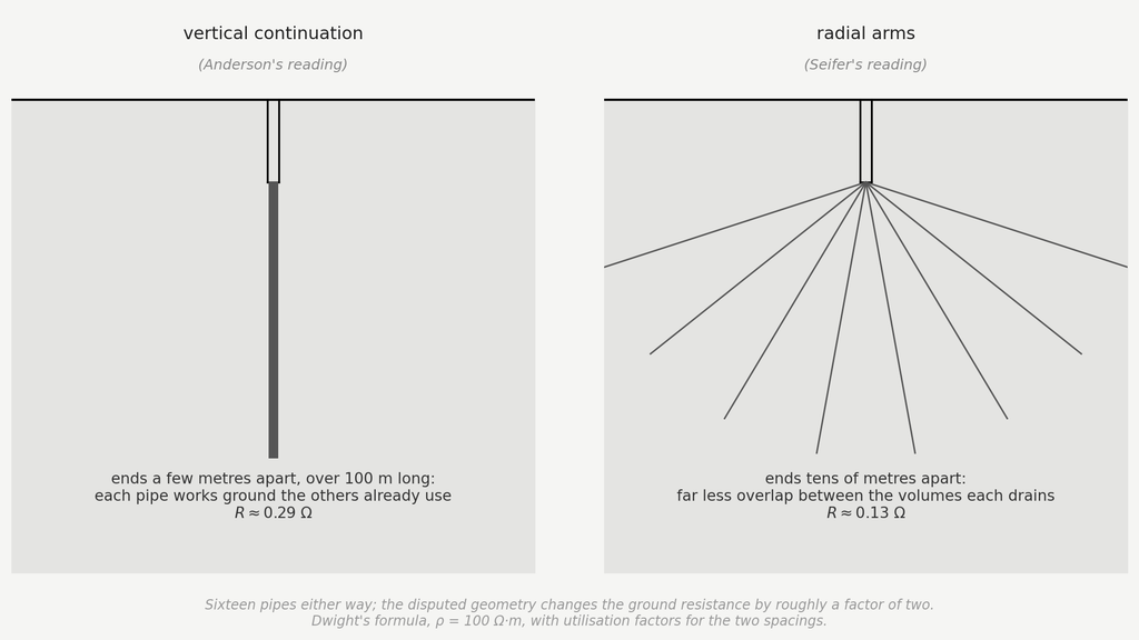
The difference matters because the resistance of a ground system depends on the extent of soil it reaches, not on how much iron it contains. A single deep pipe, however long, drains one narrow column: Dwight’s formula gives roughly 1.2 Ω. A radial fan behaves quite differently, and not for the reason one might guess — the arms are not independent electrodes, since near the hub they are centimetres apart and their fields overlap completely. What the array does is act as a disc electrode whose radius is the arm length, and the resistance of a disc falls as the inverse of its radius. For arms of this length that gives roughly 0.15–0.27 Ω, close to an order of magnitude better, with the same total iron in the ground.
One consequence worth noting is that sixteen arms are well past the point of diminishing returns: eight would give nearly the same result, since what counts is the radius reached, not the number of spokes.
That is an argument on engineering grounds rather than documentary ones, and it is worth flagging as such. But a factor of ten is not a subtlety, and a designer who had already paid to drill and drive 300 feet of pipe would have gained enormously by fanning it out rather than sinking it in a single line. The sources remain where they are; if one had to guess which arrangement a careful engineer would have chosen, the numbers point one way.
Two jobs, easily read as one
It would be a mistake to read Tesla’s conduction language as the naivety of someone unfamiliar with radio. He was, if anything, the opposite: the U.S. Supreme Court’s 1943 ruling in Marconi Wireless Telegraph Co. v. United States invalidated Marconi’s core tuning patent partly on the grounds that Tesla’s own prior patents had already disclosed the same tuned-circuit principles Marconi later claimed. Whatever else is true about the messy question of who invented radio, Tesla’s command of resonant RF circuits was real, well ahead of most of his contemporaries, and legally recognised as such.
That competence shows directly in the transmitter’s design. The resonant coil driving the elevated terminal — the “extra coil” of Tesla’s magnifying transmitter — was wound to present an electrical length near a quarter wavelength. That is the standard technique for building up a large voltage at an open, high-impedance end from a modest voltage at the driven end. The Wardenclyffe coil used the same architecture as the one at Colorado Springs but, on the available evidence, a markedly different shape: Anderson reads the drawings in patent 1,119,732 as giving a height-to-diameter ratio around 9:1, against roughly 1:1 in Colorado. Those drawings come from the patent’s 1907 renewal, however, and may reflect a later design rather than what was actually erected at Shoreham between 1901 and 1903. This is correct, sophisticated radio-frequency engineering, and it solves a specific problem: how to charge an elevated terminal to millions of volts efficiently. It says nothing, by itself, about how power gets from one station to another once that terminal is charged.
Here is the conflation worth naming directly: reading a resonant coil charging an elevated capacitive terminal, one reaches automatically for the vocabulary of radio — wavelength, radiation resistance, antenna gain — because that vocabulary is built for exactly this kind of hardware. But Tesla’s own words assign the apparatus two distinct jobs at a single frequency. The resonant stage multiplies voltage locally, so that charge can be driven into the ground at each station; the job of moving that energy from station to station is assigned, in his writing, to the Earth itself as a conductor. One frequency, two functions — and the two functions turn out to behave very differently when each is tested on its own terms.
The geometry of the local apparatus
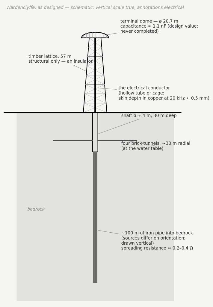
Electrically, the tower and its terminal dome form what antenna theory calls a top-loaded monopole: a vertical conductor topped by a large capacitive terminal (the dome), standing on a conducting ground plane (the Earth). The wooden lattice visible in photographs of Wardenclyffe was structural, not electrical — wood is an insulator — so the actual current-carrying path was a separate conductor, almost certainly a copper cable, run up through or alongside the wooden framework to the dome. This was standard practice for the period: low-frequency stations of that era, including Marconi’s, routinely supported their electrical conductors on wooden or lattice-steel masts that carried no current themselves. Electrically, what matters is the height the conductor spans and its own capacitance, not the material of whatever holds it up. Tower conductor and dome are the same electrical node — wired together, they rise and fall in potential as one — so their capacitances to ground simply add:
For the dome, approximated as an isolated sphere of radius a ≈ 10.3 m, the capacitance works out to about 1.1 nF — matching, reassuringly, the roughly 1 nF Tesla himself specified as a design target for the terminal. Design target is the right phrase: the dome was never finished. Photographs show partial ribbing and no completed surface, sources disagree on how far the work got, and every capacitance figure in this article is therefore computed from the intended geometry rather than measured on a built structure. The conductor’s own contribution is harder to pin down precisely, since its exact diameter is not documented in the sources consulted for this article. Fortunately the formula for a thin conductor’s capacitance depends on its radius only logarithmically, so the uncertainty barely matters: plausible radii from 1 to 20 cm all give roughly 380–590 pF. The larger end of that range would not have been a solid cable — at that thickness it would necessarily have been a hollow tube or a cage of several thinner conductors bundled to present a large effective radius. Two independent reasons favour this over solid metal, and the more fundamental of the two is skin effect. At 20 kHz, alternating current in a conductor is confined to a thin layer near its surface; in copper the skin depth at that frequency is only about 0.5 mm, so a solid rod of any real thickness would carry its current in a shell under a millimetre deep, with everything beneath it electrically inert. A hollow tube of the same outer radius carries essentially the same current at a fraction of the weight and cost — which is also, independently, the standard period technique for suppressing corona without the weight of solid metal, and the same principle behind the dome itself, which was a shell rather than a solid sphere. Either way the dome dominates, but the conductor’s own contribution is not negligible.
The dome’s real job, though, is not capacitance for its own sake. A bare vertical wire above a ground plane carries current that tapers to zero at its open top — there is nowhere left for the charge to go — which halves its effective radiating height compared to its physical height. A large capacitive top load gives that current somewhere to flow into instead of dying away, keeping it closer to uniform along the whole structure. This is the actual engineering reason for building a wide top-hat structure at all, and it is worth being precise about which of the tower’s two jobs it serves: it does help the antenna-reading of the structure, discussed next, but its more direct purpose in Tesla’s own account is charging the terminal to the voltage needed to drive current into the ground.
Testing the antenna reading first
Before turning to the conduction picture Tesla actually describes, it is worth finishing the antenna calculation this site’s earlier draft of this article was built around — because it is the reading almost every account of Wardenclyffe reaches for by default, and because knowing precisely how it fails is what makes the alternative worth taking seriously.
A vertical monopole of height h standing on a perfectly conducting ground plane produces, in the space above the plane, exactly the field of a full dipole of height 2h in free space — the missing lower half supplied by its mirror image in the conductor. For Wardenclyffe: a 57 m tower behaves, above ground, like half of a 114 m dipole.
Two corrections keep this equivalence from being used carelessly. First, the real structure only radiates into the half-space above ground, which by itself halves the radiation resistance relative to the naive free-space dipole formula. Second, the equivalence assumes a perfectly conducting ground plane, which the sandy soil of Shoreham was not.
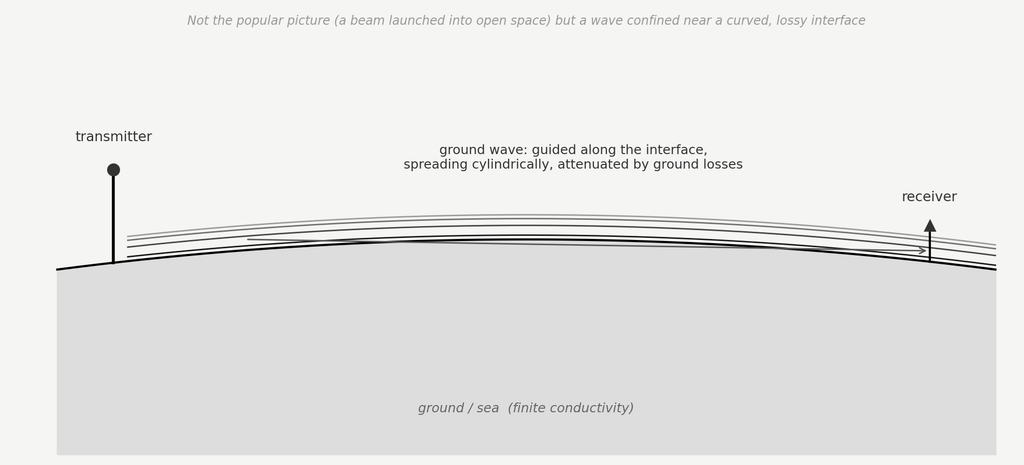
The intuitive picture of what happens next — a beam launched into open space, the way a searchlight throws a beam — is not the geometry a ground-based low-frequency transmitter produces, and if the goal really were direct station-to-station radio transmission it would need to be a ground wave: a disturbance bound to the interface between the (poorly) conducting Earth and the air above it, spreading cylindrically rather than spherically, but continuously bleeding energy into the ground it rides along.
None of that matters, however, until a more basic question is settled: how much of the power fed into the tower becomes a travelling wave at all, as opposed to heat. For a top-loaded monopole with a genuinely uniform current, image theory gives the radiation resistance over an ideal ground plane as:
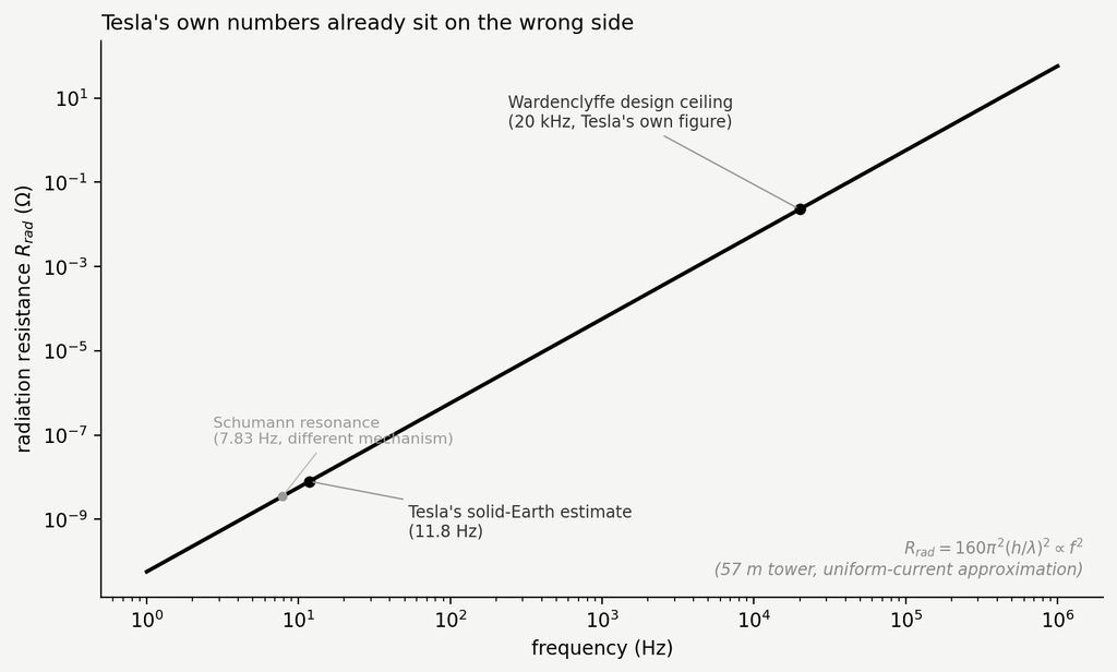
Putting in the real numbers — h = 57 m, and an operating frequency of 20 kHz, the upper bound Tesla himself specifies (his stated reason for it is examined further below) — gives a wavelength of about 15 km and a radiation resistance of:
A few hundredths of an ohm. Whatever fraction of the fed-in power actually leaves as a travelling wave is set by how this tiny resistance compares with everything else in the circuit that also consumes power:
Ground resistances for radiating structures of this kind typically run from several ohms to several tens of ohms. At 5 Ω the radiating efficiency is under half a percent; at 25 Ω, about one part in a thousand. Those typical figures are worth reading carefully: they describe stations that already have a radial ground mat installed. A tower without one does worse, not better, so for Wardenclyffe these numbers are if anything optimistic and the half-percent should be read as an upper bound.
These figures also need a word of explanation, because a later section of this article puts the ground system Tesla actually built well below one ohm. The two sets of numbers are not in conflict and cannot be compared directly, because they are not the same physical quantity — and understanding why turns out to be one of the sharpest pieces of evidence in the whole case.
The spreading resistance computed later is a direct-current quantity: the resistance from an electrode to remote earth, dominated by the material in the electrode’s immediate vicinity, and therefore improved by driving deep into conductive rock. The loss resistance that matters to a radiating monopole is something else entirely. The antenna’s return currents flow through the soil across the whole region within roughly a quarter wavelength of the base — at 20 kHz, a disc some 3.75 km in radius — and it is dissipation in that vast shallow area, not at the electrode, that consumes the power. A deep shaft does essentially nothing for it. This is precisely why real low-frequency broadcast stations do not sink shafts: they lay out radial wire mats spreading kilometres from the tower base, buried just below the surface, to intercept those return currents before they dissipate in the ground.
Tesla built the shaft. He did not build the radial mat. His grounding system was optimised, at considerable expense, for exactly the quantity that matters to a conduction machine and is nearly irrelevant to a radiating one — which is a stronger argument about what he thought he was building than anything in the written record.
Taken purely as an antenna, then, the verdict is not close. A fraction of a percent against a claimed 99.5% is not a shortfall to be closed with better engineering, and no choice of frequency rescues it: pushing lower to improve the geometric spreading only crushes the radiation resistance further, since it scales as the square of frequency. Nor does moving within the band Tesla himself specifies help — at the 5.9 Hz bottom end of his stated range, the radiation resistance of a 57 m tower falls by another seven orders of magnitude from the already-poor 20 kHz figure, to a couple of nanohms. There is no frequency, anywhere in his own window, at which this structure is a viable radio transmitter for the distances involved.
Taking the conduction language literally
This is the point at which Tesla’s own words stop fitting the antenna reading at all. He never describes station-to-station radio transmission as the long-range mechanism. He describes current entering the Earth at one station and reappearing at another, having travelled through the planet rather than around it or above it. Taken literally, this proposes a machine whose two jobs are not both radio: a resonant stage (the extra coil) that charges the elevated terminal to a high voltage, and a conduction stage that carries current between stations through the body of the Earth once that charge is dumped to ground. The frequency at which the second stage operates is not something to be guessed at — Tesla specifies it, along with two other conditions, in a patent examined below.
On this reading, the radiation-resistance collapse calculated above is not a fatal flaw. It is irrelevant, because the RF stage was never meant to radiate the intercontinental link in the first place — its job ends once it has raised the terminal to the design voltage. The question worth asking is not whether the tower radiates efficiently over thousands of kilometres. It is whether current at the frequencies Tesla specifies conducts efficiently through the Earth over that range, which is an entirely different calculation.
One clarification belongs here, because the alternative circulates widely. Many accounts of Wardenclyffe describe a two-legged circuit: current out through the ground, and back through a conducting layer in the upper atmosphere. Carlson’s biography describes the return path that way, and popular summaries go further, adding an ultraviolet beam to ionise a conduction channel deliberately.
Tesla did patent that scheme — but earlier, and it does not govern the tower. Two applications filed on the same day, 2 September 1897, cover it: U.S. 645,576 and U.S. 649,621, the first explicitly allowing the lower atmospheric strata as a conducting path, with a demonstration before the Patent Office in January 1898 showing transmission through a rarefied medium with ground return. That work predates Colorado Springs. What came after it, in the patent filed in May 1900 and covering the system Wardenclyffe was built to embody, is the passage quoted earlier: the planet behaving as a perfectly smooth conductor of inappreciable resistance, with capacitance and self-induction distributed along the axis of propagation. As Jackson notes in discussing that text, Tesla is treating the Earth as a perfectly conducting sphere in infinite space — and a sphere in infinite space has no second plate and no return path. The atmosphere is simply absent from the model.
It could hardly have been otherwise. The conducting layer that would later make sense of a two-legged circuit was not a known object in 1900: Kennelly and Heaviside proposed it independently in 1902, and it was confirmed only in 1924–25. What Tesla had was the general notion of conducting air strata somewhere high up, and his own estimate that reaching them would need an antenna some twenty-five kilometres tall. The tower is 57 metres. Whatever the 1897 patents envisage, Wardenclyffe was built for the single-path system, and that is the one tested here.
The local leg: injecting current into the ground
For a compact electrode driven into a much larger conducting medium, the resistance to remote earth is dominated by the material in the immediate vicinity of the electrode — a classical result, the same mathematics that makes the capacitance of an isolated sphere independent of where a distant return path happens to sit. The standard engineering formula for a vertical driven rod of length L and radius a, in soil of resistivity ρ, is:
Applied to roughly 100 m of iron pipe in moderately conductive rock, a single deep electrode gives about 1.2 Ω. If the iron was instead fanned out radially, as Seifer reads it, the array behaves as a disc electrode of radius equal to the arm length, and the figure falls to somewhere between 0.15 and 0.27 Ω depending on how deeply the disc sits. The honest range across both readings is therefore roughly 0.15–1.2 Ω — and the conclusion does not depend on which end of it is right.
What matters is the asymmetry, not the number. On either reading this was an excellent ground connection by the measure that governs conduction into the earth. And on either reading it did nothing whatever for the loss that governs radiation, which is dominated by dissipation across kilometres of shallow soil that no electrode, however deep, ever touches. One structure, excellent by one measure and simply irrelevant to the other: that is what discriminates between the two readings of the tower. This reframes a piece of the design that looked eccentric under the antenna reading: an ordinary radio antenna reduces ground loss with a field of shallow surface radials, not pipes driven a hundred metres into bedrock. Driving deep only makes sense as an attempt to punch through a resistive near-surface layer into more conductive material below — which is precisely what a conduction-based system, not a radiating one, would need.
The global leg: how far does the carrier actually reach
The local result is encouraging. Whether the same current can then travel usefully between continents is a separate question, and the answer is less settled — but it has to be asked at the right frequency. As the next section works through in detail, the frequency Tesla specifies for the propagating carrier is not the often-quoted 11.8; it is a band running from about 5.9 Hz at the bottom to a stated ceiling of 20 kHz at the top. The question is what happens across that band.
A first check is whether the planet is even electrically “small” at these frequencies, the condition under which a circuit description makes sense at all in place of a radiating one. It depends sharply on where in the band one sits. At the 5.9 Hz bottom end, the free-space wavelength is about 51,000 km — longer than the Earth’s circumference, though only by a factor of 1.3, which is marginal for a lumped-element description rather than comfortably within its domain. At the 20 kHz ceiling it is 15 km, thousands of times smaller than the Earth, and no such description applies. Tesla’s own stated band spans both regimes.
Consistency is not sufficiency in either case, though. An oscillating current does not travel through a lossy conductor unattenuated; it diffuses, penetrating to a characteristic skin depth that shrinks as either frequency or conductivity rises:
Evaluated across Tesla’s band in moderately conductive, water-saturated crustal rock, the penetration depth runs from roughly two kilometres at 5.9 Hz down to a few tens of metres at 20 kHz. Even the most favourable case is a small fraction of the Earth’s radius, and in most cases a small fraction of the crust’s own thickness. The current does not reach the far more conductive mantle. It stays confined to a shallow shell near the surface, and must cross intercontinental distances within that shell rather than through the planet’s bulk — and the higher in his own band the system is tuned, the thinner that shell becomes.
And here the two readings this article has been keeping apart collapse into one. A disturbance confined to a shallow shell at a conducting interface, spreading cylindrically and bleeding energy into the lossy medium as it goes, is the ground wave — the same object worked through for the radio-frequency case above, in a different vocabulary. Crustal conduction and Norton’s ground-wave propagation are not two competing mechanisms between which Tesla’s design must choose. They are the same phenomenon described twice, and the attenuation calculation for it was published by Norton in 1936.
Crustal conductivity does vary by orders of magnitude with local geology — sedimentary basins against crystalline shield rock, continental crust against ocean floor — and that variation is real. But it changes the value, not the order of magnitude of the comparison, and the comparison is not favourable: a channel confined within kilometres of lossy rock is far more dissipative than one propagating above the surface.
One general point does survive the uncertainty, and it favours a choice Tesla made anyway. Resistance per unit length along the shallow conducting shell scales as the inverse square root of the material’s conductivity, since higher conductivity lowers the resistivity and compresses the current into a thinner skin at the same time. Seawater, at roughly 4 S/m, is some four hundred times more conductive than the wet sedimentary rock assumed above — which, after the square-root scaling, still leaves an oceanic path about twenty times less resistive per unit length than a continental one. Good grounding practice had favoured wet, conductive ground over dry rock long before anyone could calculate a skin depth, and Wardenclyffe sits on a coastal site, as did most of the locations associated with Tesla’s later station proposals. The choice was very likely made for ordinary electrical reasons. It happens also to be the right one for the reason worked out here.
Tesla’s own three requirements
The two-stage picture above raises an obvious question: if a radio-frequency stage charges the terminal and a conduction stage carries the energy between stations, at what frequency does the second stage actually operate? It is tempting to answer by inventing a mechanism — a low-frequency envelope on the carrier, say, demodulated by the ground itself. Tesla’s own patent makes such invention unnecessary, and shows it to be wrong.
In U.S. Patent 787,412, Art of Transmitting Electrical Energy Through the Natural Mediums — filed May 1900, renewed June 1902, granted April 1905 — Tesla sets out three conditions he considers essential for establishing the resonant state. (They reached the file late, as the last part of this section shows; but they are the fullest statement he left of what the system needed.) They are worth taking one at a time, because they do not all constrain the same quantity, and the most-quoted number among them turns out not to be a frequency at all.
The first is geometric, and it constrains the carrier. Tesla requires that the Earth’s polar diameter be an odd multiple of a quarter wavelength — that is, of the ratio between the speed of light and four times the frequency of the currents. Worked through, 12,742 km set equal to c/4f gives a fundamental near 5.9 Hz, which matches the “six per second” he cites shortly afterwards. The odd-harmonic criterion so often attributed to Tesla originates here, and it applies to the carrier.
The second sets bounds on that same carrier. Tesla specifies that the frequency should be below 20,000 per second, with a minimum around six per second, below which — as he explains — the Earth ceases to resonate at all and behaves simply as a capacitance whose potential varies almost uniformly over its whole surface. The upper bound is worth reading carefully, because his stated reason for it is not the one this article assumed earlier: in the patent, the 20 kHz ceiling is justified by the need for oscillations whose rate of radiation into space in the form of Hertzian waves is very small — suppressing radiation, not minimising ground-wave attenuation. The attenuation reading comes from the Colorado Springs Notes and from later commentators. Two distinct criteria, arriving at the same order of magnitude for different reasons.
The third is the one that is almost universally misread, and Tesla states it with unusual precision. The most essential requirement, he writes, is that — irrespective of frequency — the wave or wave-train should continue for a certain interval of time, which he estimates at not less than about 0.08484 s: the time taken to travel to the region diametrically opposite the pole and back, at a mean surface propagation velocity of roughly 471,240 km/s.
Those two words, irrespective of frequency, do a great deal of work. The 0.08484 s figure is not a resonance, not an envelope, and not a spectral line. It is a minimum duration for each wave-train — a coherence requirement. Its operational consequence is a limit on how fast the system can be keyed: if every train must last at least 0.0848 s, the maximum signalling rate is about 11.8 symbols per second. That is a baud rate, not a frequency to be generated.
This matters because 11.8 is the number that most often escapes into secondary accounts as though it were a resonance of the Earth, and it is not. Nor is it the same quantity as the 5.9 Hz of the first requirement, despite the tidy factor of two: 5.9 Hz derives from the Earth’s diameter, while 11.8 per second derives from its circumference — 40,000 km divided by 471,240 km/s. Different geometry, different physical quantity, related by coincidence of arithmetic rather than by physics. (The velocity itself is not measured but derived: 471,240 km/s is (π/2)·c to three figures, a consequence of the surface-propagation model Tesla develops in the Colorado Springs notebooks.)
What Tesla did and did not propose about two wavelengths
Emitting more than one wavelength at once is Tesla’s own idea, and it is in the patent: he describes impressing upon the Earth two or more oscillations of different wavelength so that a resultant stationary wave travels slowly over the globe, and claims 5 and 6 cover varying the wavelengths and shifting the nodal and ventral regions respectively.
But the stated purpose is not to synthesise a low-frequency envelope. It is to make the standing-wave pattern migrate across the Earth’s surface, so that a maximum can be brought to coincide on command with a chosen receiving station. This is addressing and scanning, not coupling to a terrestrial resonance. The same reading applies to his manuscript note of 2 June 1901 on spatially modulated wave groups: concentrating energy into concentric rings, not building an ELF component.
Synchronisation to a pulse train does appear in the patent — but at the receiver, not the transmitter. Tesla describes a rotating insulating cylinder carrying metallic segments that accumulate the energy of an arbitrary number of successive impulses onto a condenser, which a second segmented cylinder then discharges into the receiver at predetermined intervals. It is a synchronous integrator, effectively coherent detection avant la lettre, and its purpose is sensitivity on weak signals. It has nothing to do with generating a low-frequency component at the transmitting end.
The distinction is worth stating plainly because the alternative reading is widespread: the interpretation of Wardenclyffe as broadcasting an ELF signal superimposed on an HF carrier belongs to K. L. and J. F. Corum, in work presented at the 1996 International Tesla Symposium, and is explicitly offered there as a reconstruction rather than as a reading of the text. Tesla’s third requirement makes such a mechanism unnecessary on his own terms: his 0.0848 s constraint is about duration, not spectrum, and nothing in the patent asks the transmitter to produce a second frequency at all.
The requirements do not fit together
Taken as a set, the three conditions are in tension, and the tension is quantifiable.
The first requirement admits any odd multiple of about 5.9 Hz; the second caps the carrier at 20 kHz. Some 1,700 admissible odd harmonics fall inside that window, spaced 11.8 Hz apart. At the top of the range this means a fractional spacing of roughly 6×10⁻⁴ — so distinguishing one admissible harmonic from its neighbour would demand a Q of order 1,700 across the entire system, Earth included. No spark-gap transmitter, however well quenched, approaches that. The first requirement is therefore very nearly non-binding in the upper part of the band Tesla himself specifies: almost any tuning falls close enough to some odd harmonic to satisfy it formally. It has real force only near the bottom, where the admissible harmonics are sparse.
This was not missed at the time. In the official action of 24 September 1903 on the application (Serial No. 112,034), the examiner observes that, given what Tesla states in the second requirement — a ventral region opposite the source and a node at the ground plate — it should be the Earth’s semi-circumference, not its diameter, that must be an odd multiple of the quarter wavelength.
The objection is more than procedural, and the physics behind it is worth spelling out, because it is the same point arrived at from a different direction. Inside a conductor, electromagnetic fields do not propagate as waves at all — they diffuse, governed by a parabolic equation rather than a hyperbolic one, on timescales set by conductivity and the square of distance rather than by any velocity. For the Earth as a whole those diffusion times run to millennia, which is why the geomagnetic field changes on geological timescales and why the geodynamo has to be explained by convective motion rather than passive field diffusion. Nothing at Tesla’s frequencies penetrates more than a few kilometres into the crust, as the skin-depth figures above already showed. A path through the Earth, along its diameter, is therefore not available to the signal at all. Whatever travels between two stations travels along the surface, and the geometrically relevant distance is an arc, not a chord.
Tesla knew this at some level, because his own third requirement uses the circumference: the 0.08484 s figure is a round trip along the surface. Yet his first requirement uses the diameter. The two cannot both describe the same signal.
There is a curious resolution buried in the numbers, and it turns on a factor of π. The Earth’s semi-circumference is π/2 times its diameter. And Tesla’s surface propagation velocity, 471,240 km/s, is π/2 times the speed of light to three figures — exactly the factor needed to make a diameter-based formula return the same answer as a semi-circumference-based one. Worked through: the quarter-wave condition on the polar diameter, evaluated at c, gives 5.88 Hz. The same condition on the semi-circumference, evaluated at Tesla’s own velocity, gives 5.89 Hz. The two π/2 factors cancel, and the fundamental frequency comes out identical either way.
None of which is a modern observation. The examiner had already made it, in the same 1903 action, and set it down in a single sentence: the applicant’s value of v is 1.57 times the value hitherto established, and that factor is the ratio of semi-circumference to diameter. He then draws the consequence with some care — if the applicant’s velocity is correct, there is no discrepancy between the first and third requirements at all.
And then he closes the trap. That velocity is not offered in the patent as a special surface-propagation figure, distinct from the speed of light and legitimately different from it. It is offered as the value of v, the same quantity everyone else had measured. So making the requirements consistent means asserting that v is half again as large as the figure “determined by Maxwell, Rowland, Hertz and many other distinguished physicists, such as Weber & Kohlrausch, Ayrton & Perry and Kelvin” — and the examiner, listing them by name, observes drily that such a startling discovery would need to be rigorously substantiated.
That disposes of the charitable reading. The π/2 factor is not a geometric conversion openly declared; it is a claim about the speed of light, made in order to reconcile two requirements that would otherwise contradict each other. It is one thing to write a condition in terms of the diameter while knowing the path is an arc. It is another to keep the diameter and adjust the speed of light to suit.
The same document settles a question of chronology, in a line easy to pass over: none of the three essential requirements were in the application as originally filed. They entered in an amendment of August 1903 — three years after the filing date, four years after Colorado Springs, and two years into construction at Shoreham. They are not the design criteria the tower was built to. They are theory written afterwards, to account for a structure that was already standing, and they arrived a month before an examiner took them apart.
His proposed remedy is worth quoting for what it says about the state of the argument: the best way out of the difficulty, he wrote, would be to cancel all reference to the first and third, and possibly the second, essential requirements, and submit a showing of operativeness together with the constants of the apparatus as a substitute for theory.
It is a small episode, and an unusually clarifying one. The system’s own designer had specified three conditions that could not all be satisfied as stated; the first person on record to notice was not a physicist but the examiner whose job was to read the claims carefully; and his advice, in the end, was to stop explaining and start demonstrating.
There is a second gap of the same kind, this one between what Tesla prescribed and what he built. The patent caps the carrier at 20 kHz. The extra coil he actually constructed and measured at Colorado Springs self-resonated at 86.8 kHz, and around 48 kHz once loaded by the antenna’s own capacitance — in both cases well above his own stated ceiling. The hardware he had in hand, and whose resonance he recorded in his notebooks, did not satisfy the requirement he was setting out in the patent he filed at the same time — the application went in on 16 May 1900, while the Colorado Springs work was still under way. He was prescribing the ceiling while the apparatus that exceeded it stood running in front of him.
What the two-function reading changes
It changes the verdict on Tesla’s engineering without rescuing the system. Read as a single radio antenna, Wardenclyffe fails by many orders of magnitude at every frequency in Tesla’s own stated band, and several of its design choices — the extreme depth of the ground system above all — look like overkill or confusion. Read as his own words describe it, one frequency serving two functions, the resonant engineering is sound and well within his demonstrated competence, and the deep grounding is exactly the right response to the problem it was actually solving: not reducing loss in an antenna, but establishing a low-resistance path for current into the Earth.
What that reading does not do is make the long-range half work. The local numbers are good. The global ones run into the medium: a current confined to a shallow shell of lossy rock, asked to cross intercontinental distances within it, is a ground wave by another name — and one routed through the most dissipative path available. Long-range propagation at these frequencies is entirely real, as VLF navigation and communication systems demonstrated for decades. It just does not happen in the rock.
What was salvageable, and what remains open
The Earth and the ionosphere really do form a resonant electromagnetic cavity, and it really does support standing-wave resonances at extremely low frequency — the phenomenon now called Schumann resonance, with a fundamental mode near 7.83 Hz. It is a different structure from the one Tesla’s writings describe, and it is worth resisting the temptation to read his 5.9 Hz figure as an anticipation of it: his number comes from a quarter-wave condition on the Earth’s polar diameter, in a model of surface conduction over the solid globe, and arrives in the same rough decade for reasons that have nothing to do with an atmospheric cavity nobody would identify for another half-century.
But the coincidence is worth sitting with, because it locates the error precisely — and the comparison is more favourable to Tesla than it first appears. Global propagation at these frequencies is real and is used: the U.S. Navy’s Clam Lake transmitter operated at 76 Hz and the Russian ZEVS at 82 Hz, both squarely inside the band Tesla specified, and both reached submarines anywhere on Earth. More than that, they worked by driving current into the ground through deep electrodes at each end of an enormous horizontal dipole — injecting current into the earth, exactly as Tesla proposed. What they did with it is where the paths diverge: the buried current closes a vast loop that radiates into the waveguide formed between the ground and the ionosphere, and the signal travels in the air above the surface, with the conducting Earth as one wall of the channel rather than as the channel itself.
So the intuition about deep grounding was right, and so was the band. What was wrong was the geometry — vertical rather than a long horizontal span — and the expectation that the Earth would carry the energy by conduction rather than serve as a boundary for a wave travelling above it. Right about the band, right about the ground connection, wrong about the path.
Near-field power transfer, for its part, is entirely real and is now a mature engineering field — inductive phone chargers and resonant coupling systems following the analysis of Kurs, Karalis, and their collaborators in 2007 exploit the reactive-field coupling Tesla was very likely observing at close range around his own apparatus. It is worth being quantitative about how sharply this fails at range: two domes of Wardenclyffe’s own dimensions, separated by a hundred kilometres, would present a mutual capacitance on the order of a tenth of a picofarad — four orders of magnitude below the roughly one nanofarad each dome holds locally against ground — and at station-to-station distances of a few thousand kilometres the figure falls to a couple of femtofarads, by which point the concept of a lumped mutual capacitance has stopped applying at all. Whatever connects distant stations, it is not direct coupling between their domes.
What is left, after the radiative and direct-coupling pictures are both ruled out, is the conduction path Tesla actually described: excellent in its local half, and in its global half the wrong side of a distinction he had no way to draw. That is a different, and more interesting, verdict than “Tesla did not understand radio.” He understood it well enough to be vindicated on a point of patent priority by the Supreme Court four decades later, and the resonant hardware he built to charge the terminal was sound. What defeated the World Wireless System was not a failure of electromagnetic reasoning but a choice of medium. The conducting layer that would have carried the signal was proposed by Kennelly and Heaviside in 1902, a year into construction at Shoreham, and confirmed experimentally by Appleton and Barnett only in 1924–25 — late enough that Tesla can hardly be faulted for not building around it, early enough that the idea was in the air while the tower still stood.
Sources
- N. Tesla, “Talking with the Planets,” Collier’s Weekly, 9 February 1901.
- N. Tesla, “World System of Wireless Transmission of Energy,” Telegraph and Telephone Age, 16 October 1927 (source of the 99.5% efficiency claim and of the 1,500 kW figure for Colorado Springs).
- N. Tesla, Colorado Springs Notes 1899–1900, ed. A. Marinčić. Beograd: Nolit, 1978 (source for the 20 kHz low-attenuation design criterion and the extra-coil measurements).
- N. Tesla, U.S. Patent 1,119,732, “Apparatus for Transmitting Electrical Energy,” originally filed 18 January 1902, renewed 4 May 1907, granted 1914. The renewal date matters: it leaves it uncertain whether the slender extra-coil geometry in these drawings documents what was actually erected at Shoreham.
- N. Tesla, U.S. Patents 645,576 (System of Transmission of Electrical Energy) and 649,621 (Apparatus for Transmission of Electrical Energy), both filed 2 September 1897, granted 20 March and 15 May 1900 (the earlier air-and-ground scheme).
- N. Tesla, U.S. Patent 787,412, “Art of Transmitting Electrical Energy Through the Natural Mediums,” filed 16 May 1900, renewed 17 June 1902, granted 18 April 1905 (the three requirements, the 20 kHz ceiling, the 0.08484 s wave-train duration, and claims 5 and 6 on varying wavelength and shifting nodal regions).
- Patent wrapper, U.S. 787,412, examiner’s action of 24 September 1903, Serial No. 112,034, pp. 38–39 (the diameter-versus-semicircumference objection; the identification of the 1.57 factor as the semi-circumference-to-diameter ratio; the observation that the three requirements were absent from the application as originally filed; and the recommendation to substitute a showing of operativeness for theory).
- J. D. Jackson, “Examples of the Zeroth Theorem of the History of Physics,” arXiv:0708.4249 (quotes patent 787,412 on the Earth as a perfectly conducting sphere, and notes that Tesla knew nothing of the ionosphere or of atmospheric conduction).
- K. L. Corum and J. F. Corum, “Spherical Transmission Lines and Global Propagation,” Proc. 1996 International Tesla Symposium, Colorado Springs (source of the ELF-on-carrier reconstruction discussed and set aside here).
- L. I. Anderson (ed.), Nikola Tesla On His Work With Alternating Currents and Their Application to Wireless Telegraphy, Telephony and Transmission of Power. Denver: Sun Publishing, 1992 (Tesla’s 1916 deposition, source for grounding-system details).
- Marconi Wireless Telegraph Co. of America v. United States, 320 U.S. 1 (1943).
- Wardenclyffe Tower, U.S. National Register of Historic Places nomination, National Park Service, 2018.
- M. J. Seifer, Wizard: The Life and Times of Nikola Tesla. New York: Citadel Press, 1996 (radial reading of the buried pipe system; cf. Anderson, above, for the vertical reading).
- A. E. Kennelly, “On the elevation of the electrically-conducting strata of the Earth’s atmosphere,” Electrical World and Engineer, March 1902; O. Heaviside, “Telegraphy,” Encyclopaedia Britannica, 10th ed., 1902; E. V. Appleton and M. A. F. Barnett, experimental confirmation, 1924–25.
- U.S. Navy ELF communications system (Clam Lake, 76 Hz) and the Russian ZEVS transmitter (82 Hz) — buried-electrode horizontal dipole antennas.
- W. O. Schumann, “Über die strahlungslosen Eigenschwingungen einer leitenden Kugel,” Z. Naturforsch. A, vol. 7, pp. 149–154, 1952.
- A. Kurs, A. Karalis, R. Moffatt, J. D. Joannopoulos, P. Fisher, and M. Soljačić, “Wireless Power Transfer via Strongly Coupled Magnetic Resonances,” Science, vol. 317, pp. 83–86, 2007.
- J. D. Jackson, Classical Electrodynamics, 3rd ed. New York: Wiley, 1998, Ch. 9 (near-field and far-field expansions; radiation resistance of short antennas).
- K. A. Norton, “The Propagation of Radio Waves over the Surface of the Earth and in the Upper Atmosphere,” Proc. IRE, vol. 24, pp. 1367–1387, 1936.
- H. B. Dwight, “Calculation of Resistances to Ground,” Electrical Engineering, vol. 55, pp. 1319–1328, 1936 (standard formula for driven-rod grounding resistance).
- Standard magnetotelluric reference values for crustal and upper-mantle electrical conductivity, as used throughout geophysical exploration literature.
Leave a Reply