The antenna built out of bad ground
From 1989 to 2004 the U.S. Navy operated a radio transmitter that consumed rather more than two megawatts and radiated about two watts. Nearly all of the rest became heat. By any ordinary measure this is not a transmitter at all; it is a very large resistor with an aerial attached.
It could also reach a submarine anywhere on Earth, at a hundred metres of depth, doing sixteen knots, without the boat coming anywhere near the surface. Nothing else could do that then, and nothing else can do it now.
The interesting part is not that it was inefficient. It is what the design gave up to work at all, and one choice in particular that looks like a mistake until the numbers are done.
There is no tower
The transmitting station at Clam Lake, Wisconsin consisted of two lines of wire, each about 22 km long, crossing at right angles with the transmitter building at the intersection. A second station at Republic, Michigan added three more lines in a rough F, the shape dictated by which land could be obtained rather than by anything electrical. Between them, 135 km of line.
The lines ran on ordinary wooden utility poles, at ordinary heights, and looked exactly like what they resembled: rural power distribution. Photographs of the site show forest with a cleared right-of-way running through it. Someone driving past would have seen nothing worth a second glance.
At each end, the line went into the ground. Initially through a mile or more of buried copper cable and ground rods; later through arrays of electrodes in boreholes 300 feet deep.
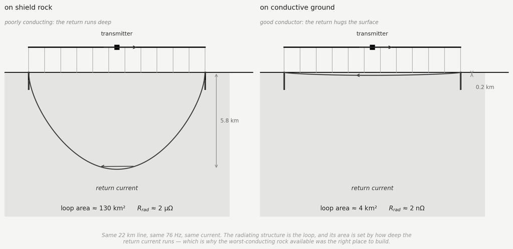
That is the whole antenna. Current leaves the transmitter, travels along the overhead line, enters the earth at one end, returns through the ground, and comes back up at the other. The radiating structure is not the wire. It is the loop — a vertical circuit whose top edge is the line you can see and whose bottom edge is a return path kilometres underground.
Why the ground had to be bad
The two stations sit on the Laurentian Shield, and the sources are explicit that this was the reason for choosing the location: the shield is a very large area of very poor conducting rock.
Read as ordinary engineering that is backwards. Every rule about grounding says to look for conductive, wet, mineral-rich ground, and to avoid dry crystalline rock. Here they went looking for the worst conductor on the continent and built on it deliberately.
The reason is the loop. What radiates is the area the circuit encloses, and that area is set by how deep the return current runs. The governing scale is the skin depth:
which grows as the conductivity falls. In wet, conductive ground at these frequencies the return current hugs the surface, a couple of hundred metres down, and the circuit it closes is a thin ribbon. Under the shield it runs kilometres deep, and the loop becomes a sheet of circuit standing on edge in the crust.
The effective depth is not quite the skin depth of a uniform half-space, because the crust is layered and the current stops where the conductivity rises. The published figures for the two systems make this concrete. Beneath the American antennas the average effective conductivity is about 2.4×10⁻⁴ S/m, giving a working depth near 2.6 km. Under the Kola Peninsula, where ZEVS was built, the first layer is some ten times more resistive still — about 10-5 S/m — and runs about 10 km down before a far more conductive layer stops it. Ten kilometres of usable depth, from ground chosen for being nearly an insulator.
There is a second way to see the same thing. The return current flows opposite to the current in the line, so its field partly cancels the field of the line — this is exactly why a wire lying on a perfect conductor radiates nothing at all. What separates the two currents is depth. Poor conductivity buys separation, and separation is the only thing standing between this antenna and complete self-cancellation.
The numbers, and the other station
The figure of merit ELF designers actually use is not gain or radiation resistance but the magnetic moment of the loop — current, times line length L, times effective depth W:
For the two American antennas together, at 300 A each, 22.5 km long, over 2.6 km of usable depth, that comes to about 3.5×10⁴ A·km².
The Russian station is the useful comparison, because it is the same idea built on different ground. ZEVS sits on the Kola Peninsula near Murmansk: two parallel grounded lines about 60 km long running east–west, driven at 200–300 A, transmitting at 82 Hz. Its moment works out near 1.1×10⁵ A·km² — roughly three times the American figure, which in radiated power is the 10 dB advantage reported when Stanford receivers first picked it up worldwide in January 1990.
Where that advantage comes from is worth reading off the formula. ZEVS runs less current than the American system. It wins on the other two factors: lines nearly three times as long, over ground nearly four times deeper. It is a better antenna mostly because it stands on worse rock.
As for how much actually leaves: a few watts, on both systems. It is worth being careful about where that figure comes from. Treating the circuit as an ordinary small loop radiating into free space,
gives a radiation resistance of order a microohm and, at the documented currents, a couple of tenths of a watt — an order of magnitude below the few watts the operators report. The discrepancy is not arithmetic. A free-space loop formula is the wrong tool here, because the antenna is not radiating into free space: it is launching a mode into the cavity between the ground and the ionosphere, and the coupling to that mode is what sets the output. The free-space estimate is useful for showing the order of magnitude and for comparing one geometry against another; it is not the design calculation.
What is not in doubt is the efficiency. A few watts out of some two and a half megawatts in is under one part per million:
Everything else — better than 99.9999% of the input — warms up Wisconsin, or the Kola Peninsula.
Why that frequency, and what replaced it
Nothing about this design is a free choice. Every feature of it — the hundred kilometres of wire, the megawatts, the deliberate hunt for bad rock — follows from one number, and that number comes from seawater.
Salt water is a conductor, and a conductor screens. A signal entering the ocean dies away over the same skin depth of Formula 1, now with the conductivity of seawater, about 4 S/m. In the VLF band around 20 kHz that distance is under two metres: a boat has to come to periscope depth and put an antenna near the surface, which is exactly what a submarine exists not to do. At 76 Hz it is about twenty-nine metres, and the boat can stay deep and fast. That single factor of sixteen is the entire justification for the enterprise.
Which is also why the whole system is built around the magnetic field and never the electric one. Seawater does not merely attenuate an electric field, it shorts it out: the free charges rearrange and cancel it, in the way any conductor does. The magnetic field is attenuated, by the skin depth above, but it is not suppressed by that mechanism, and it survives. So the receivers are magnetometers — ferromagnetic-cored solenoids on a trailed antenna in the ordinary case, and triaxial SQUID arrays, specified at around ten femtotesla per root hertz, in the version built for the deepest and fastest boats. That closes the circle back to the transmitter: the design figure at one end is a magnetic moment, and the sensor at the other end measures a magnetic field. The electric field never enters the useful account at either end.
The amplitudes involved are worth stating, because they are the other half of why the bandwidth is what it is. A field of order a picotesla at the surface, attenuated through a hundred metres of seawater, arrives at the boat as a few tens of femtotesla — something like a billionth of the Earth’s own steady field, in which the sensor is sitting, and below the natural background of lightning and Schumann resonance in the same band. Pulling a signal out of that takes a very narrow bandwidth and a long integration, which is another way of saying: a few characters per minute.
The bill for it is bandwidth. At these frequencies there is essentially none: the system sent short coded messages at a few characters per minute, one way, with no possibility of a reply — the transmitter needed a hundred kilometres of antenna, and no submarine carries one. In practice it was a bell rather than a telephone: a signal telling a boat to come shallow and listen properly on a faster channel.
Which is, in the end, how it was superseded. Project ELF was shut down in September 2004, declared obsolete in favour of improved VLF systems. The replacement does not solve the seawater problem — nothing solves the seawater problem — it goes around it by moving the receiver instead of the signal: towed buoys and trailing wire antennas that a submarine streams close enough to the surface to use ordinary VLF, while the hull stays deep. That is better engineering, and it also concedes the point the ELF system had been built to avoid. Something has to come up. For fifteen years, nothing did.
ZEVS, by the available accounts, is still there.
An echo
One detail is hard to pass over. The final grounding arrangement at these stations was arrays of electrodes in boreholes 300 feet deep.
Three hundred feet of iron pipe driven into bedrock is also, to the foot, what Tesla had sunk beneath Wardenclyffe eighty years earlier, and for the same stated reason: to get a grip on the earth. Two projects with almost nothing else in common — one a private venture built on a misconception, the other a cold-war military system built on correct theory — arrived at the same answer to the same narrow question of how to put current into the ground.
They diverge immediately afterwards, and the divergence is the whole difference between them. Tesla ran his conductor up, into a single elevated terminal, and expected the Earth to carry the energy onward by conduction. These stations run their conductor sideways, twenty kilometres to a second ground point, and expect nothing of the Earth except that it close a circuit and stay out of the way. What radiates is the loop; what carries the signal is the waveguide between the ground and the ionosphere, with the energy travelling in the air above the surface rather than in the rock below it.
Same band, same grounding problem, same solution to it — and opposite conclusions about what the planet is for.
Sources
- Project Sanguine and Project ELF: transmitter geometry at Clam Lake, Wisconsin and Republic, Michigan; 84 miles of above-ground line; grounding by buried cable and by electrode arrays in 300 ft boreholes; the 1968 proposal for a 6,000-mile buried grid over 22,500 square miles.
- U.S. Navy operational descriptions of the ELF system, 76 Hz, one-way messaging to submerged submarines; Clam Lake trials of 1983–84 (communication with a boat at 400 ft and 16 knots); shutdown in September 2004.
- ZEVS, Kola Peninsula: two parallel grounded lines about 60 km long, east–west, 82 Hz, 200–300 A. E. P. Velikhov et al., 1996 and 1998; A. C. Fraser-Smith, “Reception of ELF signals at antipodal distances” (Stanford), on the worldwide reception of the 82 Hz transmissions in January 1990 and the 10 dB advantage over the American system.
- Ground conductivity and effective depth figures for both sites (2.4×10⁻⁴ S/m and W ≈ 2.6 km beneath the American antennas; a resistive first layer of about 10-5 S/m to some 10 km depth under the Kola Peninsula), and the magnetic-moment comparison, from the technical summaries at vlf.it.
- Michigan Technological University, Military History of the Upper Great Lakes, student research pages on the Clam Lake and Republic installations (source for the input power, the radiated power, and the choice of the Laurentian Shield for its low conductivity).
- Submarine ELF reception: development of triaxial SQUID receiving antennas with sensitivity of order 10-14 T·Hz-1/2, and detection of the Wisconsin transmitter at 100 m depth (IEEE literature on superconducting ELF magnetic field sensors).
- Radiation resistance of an electrically small loop: standard antenna theory, e.g. C. A. Balanis, Antenna Theory: Analysis and Design.
- Skin depth and seawater attenuation: J. D. Jackson, Classical Electrodynamics, 3rd ed., ch. 5 and 7.
- Wardenclyffe grounding: L. I. Anderson (ed.), Nikola Tesla On His Work With Alternating Currents, 1916 deposition; discussed at length in The Antenna That Wasn’t One on this site.
Leave a Reply